


Bypass Factory Amp/Crossover in 2002 Chevy Tahoe

This article strays a bit from home automation, but it was a small project that I completed recently and felt that others could benefit from a detailed write up with step-by-step instructions and pictures.
I recently found myself needing to replace almost every speaker in my 2002 Chevy Tahoe (non-Bose sound system). The factory speakers were all blown and sounding pretty pitiful. In fact I did not realize how bad it was until I removed the old factory speakers and noticed cone separation on every door speaker and the factory subwoofer.
In addition to replacing the speakers, I came across a forum post on z71tahoe-suburban.com that discussed bypassing the factory amplifier for each of the door speakers. It turns out that all the door speakers are routed thru the factory amplifier. I am not sure that it provides amplification to the door speakers, but it does have an internal crossover that removes much of the bass from the audio signal. Since I replaced all the door speakers with a better set of component speakers capable of handing more of the full audio range, I did not want the factory amp/crossover restricting the audio signal from the head unit (receiver) to the door speakers.
The forum post included a detailed set of instructions on how to build an adapter cable that will plug directly into the factory wiring harness and the factory amplifier and bypass the factory crossover for the four door speakers. This bypass cable does still send audio and power to the factory amplifier for the rear cargo area subwoofer and pillar tweeters. (If you don't need the factory amp because you are using an after-market amplifier, then you may choose not to include that portion of the cable or just not plug the adapter back into the factory amplifier.) This is a 100% non destructive modification to the Tahoe. This bypass adapter can be removed at any time.
Parts List
;) (click image to enlarge)
(click image to enlarge)
The following parts are required.
Approximate Cost: $20-25 USD
Total Time: 1-2 hours
NOTE: You may notice that these wiring adapters describe that they are for a Saturn vehicle. Just ignore that, we are not going to use them as they are wired, we are going to reconfigure the wiring. We just need these as they are the correct connectors that will work with the Tahoe's factory wiring harness and factory amplifier.
Tools & Supplies
I used the following tools and supplies to complete this project:
;) (click image to enlarge)
(click image to enlarge)
- Wire Cutters
- Wire Strippers
- Small Flat Screwdriver
- Small Paperclip
- Large Paperclip
- CD/DVD Drive Eject/Release Tool (optional)
- Solder Iron
- Solder
- Solder Paste (optional)
- Small Nylon Wire Ties (optional)
- Assorted sized and color heat shrink tubing
- Heat Gun (or hair dryer, or cigarette lighter)
- Digital Multi-meter for continuity testing (optional)
- Table/Bench Vise (optional)
- Helping Hands with Alligator Clips (optional)
NOTE: If you are not comfortable with soldering, you could use wire nuts (twist on wire connectors, b-caps) instead to make each wiring connection. This take up more room, but is perfectly viable. Just make sure to use electrical tape or some means to ensure that the wire connectors don't vibrate loose and fall off over time.
Assembly
We are basically going to use the two Metra GM connectors to create a bypass cable that will be installed in between the Tahoe's factory wiring harness and the factory amplifier/crossover.
<< STEP 1 >> - Disassemble the Metra 70-2002 Connector
The first step is to remove all the existing pins and wires from the Metra 70-2002 connector. The pins are released by inserting a small paperclip below each pin and using a push and pull technique on the wire until the pin is released. Don't use force to remove these pins, we will need to reuse each pin and wire.
;) (click any image above to enlarge)
(click any image above to enlarge);)
;)
<< STEP 2 >> - Disassemble the Metra 71-2002 Connector
The next step is to disassemble the Metra 71-2002 connector. Before removing the pins and wires, we must first remove the two retaining clips (gray and blue). Lets start with the gray clip. Gently insert the end of a small flat screwdriver between the connector and the clip's retention clasp. Repeat this for each side of the clip. Once released, pull the clip towards the rear of the connector to remove it. Next we need to remove the blue clip. For the blue clip we must insert the end of the screwdriver to release the retention clasp from the front side of the connector. Repeat this on both sides and then gently pull back the clip towards the rear of the connector to remove it.
;)
;)
;)
;)
(click any image above to enlarge)
With the two clips removed, we can now remove each pin and wire. To remove the pins in this connector, insert either the end of the large paper clip or the end of a CD/DVD disc removal tool into the face of the connector as show below to release the pin. (I found that the diameter of the CD/DVD disc removal tool was slight larger than the paperclip and was a little easier to use.) Use the push and pull technique on the wire to remove it from the connector. Again, don't use force to remove these pins, we will need to reuse a few of the pins and wires. The pins will easily slide out towards the rear of the connector once properly released.
;)
;)
;)
;)
(click any image above to enlarge)
<< STEP 3 >> - Rewire the Connectors
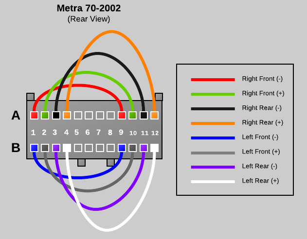
The next step is to reinstall the wiring between the Metra 70-2002 connector and the Metra 71-2002 connector. The wiring diagram below is what we will be building.
;)
Wiring Connection Legend
- Right Front (Negative) - [70] A1 to [70] A9 - RED
- Right Front (Positive) - [70] A2 to [70] A10 - GREEN
- Right Rear (Negative) - [70] A3 to [70] A11 to [71] A11 - BLACK
- Right Rear (Positive) - [70] A4 to [70] A12 to [71] A12 - ORANGE
- Power Antenna - [70] A5 to [71] A5 - YELLOW
- Left Front (Negative) - [70] B1 to [70] B9 - BLUE
- Left Front (Positive) - [70] B2 to [70] B10 - GRAY
- Left Rear (Negative) - [70] B3 to [70] B11 to [71] B11 - PURPLE
- Left Rear (Positive) - [70] B4 to [70] B12 to [71] B12 - WHITE
WIRE 1 - RIGHT FRONT SPEAKER - NEGATIVE (A1 to A9)
Note that the red wire removed from the Metra 70-2002 Connector includes three pins and two short and one long wire segments. Cut the second short wire segment as close as possible to the pin connector so that you have a single short segment with two pins attached. Next, insert the pins into the rear of the Metra 70-2002 Connector in positions A1 and A9. If the pin does not stay in place, you may need to take the screwdriver and bend the clasp on the pin back so that it can catch properly.
;) (click any image above to enlarge)
(click any image above to enlarge);)
;)
WIRE 2 - RIGHT FRONT SPEAKER - POSITIVE (A2 to A10)
Wire 1 was the easy one, the remaining wires will have to be soldered together (or connected using an alternate electrical connector). Basically we need to connect two of the wires with pins together to create a single wire with a pin on each end. Wire two is a simple straight connection using the green and green with black stripe wire leads from the Metra 70-2002 connector. I trimmed the lengths down to eliminate bulk, but that is optional. Cut, strip the insulation and solder the two ends of the green leads so that you end up with a single wire with a pins on each end. Insert a length of heat shrink tubing around the connection and heat to shrink. Finally insert the pins into position A2 and A10 of the Metra 70-2002 connector.
;) solder two leads
solder two leads
;) place heat shrink
place heat shrink
;) heat to shrink
heat to shrink
;) insert into connector
insert into connector
WIRE 3 - RIGHT REAR SPEAKER - NEGATIVE (A3 to A11 to A11)
Wire 1 and wire two were straight connections that bypass the factory amplifier completely. Wire three is slightly different because it also feeds the amplifier the rear audio signal so that the factory amplifier can drive the cargo area subwoofer and pillar tweeters. If you do not want to use the factory amplifier at all you can leave out the A11 connection to the Metra 71-2002. The next wire is a connection using the black and black with white stripe wire leads from the Metra 70-2002 connector and the black wire from the Metra 71-2002 connector. Cut, strip the insulation and solder the three ends of the black leads so that you end up with a wire with two Metra 70-2002 pins and one Metra 71-2002 pin. Before soldering make sure to stage a length of heat shrink tubing around the connection and after soldering slide the heat shrink tubing into place and heat to shrink. Finally insert the pins into position A3 and A11 of the Metra 70-2002 connector and also A11 of the Metra 71-2002 connector.
;) 70-2002 close up
70-2002 close up
;) both connectors
both connectors
;) 71-2002 close up
71-2002 close up
WIRE 4 - RIGHT REAR SPEAKER - POSITIVE (A4 to A12 to A12)
Repeat the same steps as wire three using the orange and orange with yellow stripe wire leads. Insert the pins into position A4 and A12 of the Metra 70-2002 connector and also A12 of the Metra 71-2002 connector.
;) 70-2002 close up
70-2002 close up
;) 71-2002 close up
71-2002 close up
WIRE 5 - POWER ANTENNA (A5 to A5)
Wire 5 is a simple straight through connection from A5 of the Metra 70-2002 connector to A5 of the Metra 71-2002 connector using the yellow wire leads
;) 70-2002 close up
70-2002 close up
;) 71-2002 close up
71-2002 close up
WIRE 6 - LEFT FRONT - NEGATIVE (B1 to B9)
WIRE 7 - LEFT FRONT - POSITIVE (B2 to B10)
Wire 6 and 7 are both simple straight bypass connection just like wire 1 and 2 except that they are installed on the "B" side of both connectors. Wire 6 uses the blue with yellow strip and the tip of the red wire from the Metra 70-2002 connector. There were not two blue leads and we need to reuse every pin, so I used just the tip of the remaining red wire lead and trimmed off the extra red wire. See the photo for details. Wire 6 should be inserted into positions B1 and B9 on the Metra 70-2002 connector. Wire 7 uses the gray and gray with black strip wire leads from the Metra 70-2002 connector and should be inserted into positions B2 and B10 on the Metra 70-2002 connector.
;) Wire 6 - Blue
Wire 6 - Blue
;) Wire 7 - Gray
Wire 7 - Gray
WIRE 8 - LEFT REAR - NEGATIVE (B3 to B11 to B11)
WIRE 9 - LEFT REAR - POSITIVE (B4 to B12 to B12)
Wire 8 and 9 are identical to wires 3 and 4 except that they are installed on the "B" side of both connectors. These wires provide the rear audio signal for the factory amplifier to deliver sound to the factory subwoofer and pillar tweeters in the cargo area. Wire 8 uses the purple and purple with black stripe wire leads from the Metra 70-2002 connector and the purple with black stripe wire from the Metra 71-2002 connector. Wire 8 should be inserted into positions B3 and B11 on the Metra 70-2002 connector and position B11 on the Metra 71-2002 connector. Wire 9 uses the white and white with black stripe wire leads from the Metra 70-2002 connector and the white wire from the Metra 71-2002 connector. Wire 9 should be inserted into positions B4 and B12 on the Metra 70-2002 connector and position B12 on the Metra 71-2002 connector.
;) Wire 8 (70-2002 close up)
Wire 8 (70-2002 close up)
;) Wire 8 (71-2002 close up)
Wire 8 (71-2002 close up)
;) Wire 9 (70-2002 close up)
Wire 9 (70-2002 close up);) Wire 9 (71-2002 close up)
Wire 9 (71-2002 close up)
WIRING COMPLETE
That all the wiring steps, next, we will test the connections and complete the assembly.;) Wiring Completed (click image to enlarge)
Wiring Completed (click image to enlarge)
<< STEP 4 >> - Testing
If you have a multi-meter or continuity tester, its a good idea to test all the pins to make sure that the connectors are wired correctly before installing into the Tahoe. Set the multi-meter to continuity testing mode and then test the following pins in the Metra 70-2002 connector and make sure there is a connection between them. Also touch the other pins to ensure that no other pins have a connection for each test.
- A1 to A9
- A2 to A10
- A3 to A11
- A4 to A12
- B1 to B9
- B2 to B10
- B3 to B11
- B4 to B12
Next let's test the Metra 71-2002 connector. To do this you can use the small paper clip to insert into each pin for testing. Ensure the following connection are valid:
- Metra 70-2002 A5 to Metra 71-2002 A5
- Metra 70-2002 A11 to Metra 71-2002 A11
- Metra 70-2002 A12 to Metra 71-2002 A12
- Metra 70-2002 B11 to Metra 71-2002 B11
- Metra 70-2002 B12 to Metra 71-2002 B12
;) Multi-meter / Continuity tester
Multi-meter / Continuity tester;) test Metra 70-2002
test Metra 70-2002;) test Metra 71-2002
test Metra 71-2002
<< STEP 4 >> - Tidy Up
All tests passed? Great! Let's finish by re-installing the retention clips in the Metra 71-2002 connector and and adding a few nylon wire ties to tidy up this bypass connector.
;) blue clip
blue clip;) gray clip
gray clip;) Metra 71-2002 - complete
Metra 71-2002 - complete
Install a few nylon tie straps and trim all the excess strapping.
;)
Installation
Now that your have constructed the bypass adapter, the installation inside the truck is very simple. Empty the glove box and then depress the right side towards the drivers side of the vehicle to allow the glove box door to open completely and drop open.
Next, locate the factory amplifier directly to the right of the cabin air filter on the right side of the glove box cavity.
;)
;)
Next, release the mounting retention clip located on top of the amplifier.
;)
;)
Tilt the amplifier up to gain easier access to the wiring connectors plugged into the amplifier. Unplug the lower wiring connector from the amplifier. There is a release on the back side of the connector, you must depress this release before the plug can be removed from the amplifier.
;)
;)
Insert the Metra 70-2002 connector on the bypass adapter into the vehicles wiring harness. Insert the other end of the bypass adapter (the Metra 71-2002 connector) into the factory amplifier. Don't worry, you can't screw this up, the plugs only fit in their correct locations.
;)
;)
Tuck the bypass adapter away above the amplifier so that does not interfere with the glove box. Put the amplifier back in place and re-attach the retention latch and then raise the glove box and fire up your stereo for a test. That's it -- we are all done!
;)
More Information / Source
More information about the wiring harness in the Tahoe and more specific details about this adapter can be found in this document:
Please note: the wiring coloring scheme used in this document is different than what is posted in this article. The article used the best mix of colored wires based on what came in the Metra connector packages and trying to remain as consistent as possible for all connection leads.
This document was originally posted on this forum posting:
 Robert Savage
If you are not interested in using the 2002 Tahoe's factory amplifier, rear pillar tweeters, and factory sub, then you only need the Metra 70-2002 connector and not the Metra 71-2002.
The wiring is bascially the same except that no wire leads extend to the second connector. This version of the adapter just bypasses the factory amplifier/crossover and sends the pure unfiltered audio signals to all the door speakers.
UPDATE 2019-07-02
A number of user comments suggest that you can simply purchased Metra #70-2021 if you wish to do a complete bypass of the factory amp. I have not personally verified or tested this, but it may be worth a try or further investigation for an easier off-the-shelf install.
Reader Comments (159)
Thanks for posting this. I have two questions:
1. I'm getting a bad noise out of the front left speakers when its cold. Do you think that it's the amp or the speaker?
2. If I bypass the amp, do you think the head unit is powerful enough for cranking up good tunes? Don't know how else to put it.
Thanks for your help.
@Nshaw,
I am not a car audio expert, but I would suspect the speaker first. If you bypass the amp and are still using the factory head unit, it probably is not powerful enough to produce decent audio while bypassing the amp since it was designed for use with the factory amp. I replaced my factory head unit with an aftermarket head unit and the aftermarket head unit is certainly capable of delivering the necessary power if you bypass the factory amp. I ended up replacing all door speakers and the head unit in my Tahoe. Most of the door speakers were blown/defective. The speaker cone materials had all disintegrated leaving behind terrible audio. The new speakers sound great!
Robert:
Thanks for posting this. This is much better than spending a few hundred bucks on a new 5 channel amplifier.
Does it really matter which harnesses you get? As long as you use compatible harness/reverse harnesses, and you wire the corresponding wires properly, it shouldn't matter. Right?
Thanks!
Hi GaryB,
You are right in that it really does not matter which harness so long as the connectors are the correct ones. However, it has been reported that some of these GM harnesses with the correct connectors don't include enough pins and wires in the connector. So the model illustrated and referenced here includes the exact number of pins, no more - no less. So no room for errors :-) If you find a better model (with more pins/wires), let me know and I can include a comment above with the model number for others to see.
Happy New Year!
Robert
Thanks for posting this! I am working on it now.
Just an FYI though...the diagram under "Step 3" shows the yellow power antenna wire going to A8 on the Metra 71-2002 instead of A5.
@Sam,
Thanks for catching that error! I have fixed and updated the drawing.
-Robert
I just did this bypass and cannot get sound to the woofer or pillar speakers. I have continuity on the A5 connections which i assume powers the amp and sends audio to the woofer and speakers when pluggged in. What am I missing, I'm stumped? Door speakers all work great with increased bass response, just no sound in the back. My connections look exactly like the above just different colored wires.
Any help or incite on what to try to get it to work would be great. I have upgraded door speakers with Infinity speakers and would like to have the rear pillars and woofer to work.
Thanks,
Al
Just did this mod last night. Was easy to do and for $14 (ebay) I am very happy with it.
Thanks for the diagram. My amp died due to my ALPINE install, which lasted 4 years. I connected a small speaker directly to stereo and placed between front seats for about 2 months now. I didn't want to cut up stock wiring and this diagram helped me out.
I went to pep boys and they had Metra 80-2002 and not the 70-2002 connector. But it had enough to get the job done. was $18. Worth being able to put it all back to stock later if i plan on selling truck.
If your not in a hurry you can find online for $8 plus shipping. Maybe worth waiting to save a couple bucks. I just didn't really care and wanted to do it now on my free day.
Thanks again
@pRoFiT,
Glad to hear the diagrams were helpful for your project. Also ... thank you for posting the alternate Metra part number -- that could be helpful for others if they are trying to locally source the parts.
-Robert
thank you very much for this posting it was fantastic I made the parts hooked it up my stereo works again!
the factory amp lost the left channel sound so the new head unit powers everything now sounds great
@Rob,
Thanks for the comment -- glad the article was helpful. I too was surprised at how decent the Tahoe could sound with a new head unit. Of course the new Kenwood component door speakers and new Kicker subwoofer I added didn't hurt matters.
-Robert
What a beautifully detailed and well illustrated article. Thank you for creating it. I know and appreciate how much time and effort it takes to produce clear and comprehensive technical information, that is still mentally accessible to non technical folks. You do a great job at that. I don't even have the vehicle referenced in your article, but I can still appreciate the patience you had to produce it. Thanks again!
Hey there. Would you build one of these bypass for me. Please let me know what you charge. I have a 2001 chevy tahoe. Non bose system.
Hello. I appreciate you going thru all this detailed info on how to bypass..I followed every bit of instruction and got every thing to work except the left rear speaker. I removed the new bypass that i created and retested. It all tests fine. I also plugged the old harness in and the left rear work fine. So I am stumped. I would appreciate some help on this. Its a 02 suburban non bose. Thansk Nick
What about the yellow power antenna wire..Is it supposed to be A5 or A8 position. Thanks Nick
@Bdub
I'm sorry, but i am not in the position to build and sell adapters at this time.
Perhaps another reader here or in the forums could help out:
http://z71tahoe-suburban.com/iboard/index.php?showtopic=37
Thanks, Robert
@Nick
Power Antenna Lead:
I looked at the original documentation to verify A5 to A5 and it looks correct. See this document for details:
http://www.savagehomeautomation.com/storage/post-images/tahoe-bypass/Factory_High_Pass_Crossover_Bypass_Tahoe_02.pdf
Left Rear Speaker:
You might want to use a multimeter and test continuity on wire #8 and #9:
WIRE 8 - LEFT REAR - NEGATIVE (B3 to B11 to B11)
WIRE 9 - LEFT REAR - POSITIVE (B4 to B12 to B12)
Also compare with the instructions here to make sure I did not miss anything:
http://www.savagehomeautomation.com/storage/post-images/tahoe-bypass/Factory_High_Pass_Crossover_Bypass_Tahoe_02.pdf
Thanks, Robert
Great article, hugely helpful! I just (almost) completed this last night, but found that the 70-2002 harness I ordered from Amazon came without a Black/White wire and pin, so I ended up one pin short. I'll be stopping by my local auto parts store for whatever their cheapest harness is today so I can harvest a wire/pin from that to finish the job...
does this bypass the factory amp all entirely??