


Bypass Factory Amp/Crossover in 2002 Chevy Tahoe

This article strays a bit from home automation, but it was a small project that I completed recently and felt that others could benefit from a detailed write up with step-by-step instructions and pictures.
I recently found myself needing to replace almost every speaker in my 2002 Chevy Tahoe (non-Bose sound system). The factory speakers were all blown and sounding pretty pitiful. In fact I did not realize how bad it was until I removed the old factory speakers and noticed cone separation on every door speaker and the factory subwoofer.
In addition to replacing the speakers, I came across a forum post on z71tahoe-suburban.com that discussed bypassing the factory amplifier for each of the door speakers. It turns out that all the door speakers are routed thru the factory amplifier. I am not sure that it provides amplification to the door speakers, but it does have an internal crossover that removes much of the bass from the audio signal. Since I replaced all the door speakers with a better set of component speakers capable of handing more of the full audio range, I did not want the factory amp/crossover restricting the audio signal from the head unit (receiver) to the door speakers.
The forum post included a detailed set of instructions on how to build an adapter cable that will plug directly into the factory wiring harness and the factory amplifier and bypass the factory crossover for the four door speakers. This bypass cable does still send audio and power to the factory amplifier for the rear cargo area subwoofer and pillar tweeters. (If you don't need the factory amp because you are using an after-market amplifier, then you may choose not to include that portion of the cable or just not plug the adapter back into the factory amplifier.) This is a 100% non destructive modification to the Tahoe. This bypass adapter can be removed at any time.
Parts List
;) (click image to enlarge)
(click image to enlarge)
The following parts are required.
Approximate Cost: $20-25 USD
Total Time: 1-2 hours
NOTE: You may notice that these wiring adapters describe that they are for a Saturn vehicle. Just ignore that, we are not going to use them as they are wired, we are going to reconfigure the wiring. We just need these as they are the correct connectors that will work with the Tahoe's factory wiring harness and factory amplifier.
Tools & Supplies
I used the following tools and supplies to complete this project:
;) (click image to enlarge)
(click image to enlarge)
- Wire Cutters
- Wire Strippers
- Small Flat Screwdriver
- Small Paperclip
- Large Paperclip
- CD/DVD Drive Eject/Release Tool (optional)
- Solder Iron
- Solder
- Solder Paste (optional)
- Small Nylon Wire Ties (optional)
- Assorted sized and color heat shrink tubing
- Heat Gun (or hair dryer, or cigarette lighter)
- Digital Multi-meter for continuity testing (optional)
- Table/Bench Vise (optional)
- Helping Hands with Alligator Clips (optional)
NOTE: If you are not comfortable with soldering, you could use wire nuts (twist on wire connectors, b-caps) instead to make each wiring connection. This take up more room, but is perfectly viable. Just make sure to use electrical tape or some means to ensure that the wire connectors don't vibrate loose and fall off over time.
Assembly
We are basically going to use the two Metra GM connectors to create a bypass cable that will be installed in between the Tahoe's factory wiring harness and the factory amplifier/crossover.
<< STEP 1 >> - Disassemble the Metra 70-2002 Connector
The first step is to remove all the existing pins and wires from the Metra 70-2002 connector. The pins are released by inserting a small paperclip below each pin and using a push and pull technique on the wire until the pin is released. Don't use force to remove these pins, we will need to reuse each pin and wire.
;) (click any image above to enlarge)
(click any image above to enlarge);)
;)
<< STEP 2 >> - Disassemble the Metra 71-2002 Connector
The next step is to disassemble the Metra 71-2002 connector. Before removing the pins and wires, we must first remove the two retaining clips (gray and blue). Lets start with the gray clip. Gently insert the end of a small flat screwdriver between the connector and the clip's retention clasp. Repeat this for each side of the clip. Once released, pull the clip towards the rear of the connector to remove it. Next we need to remove the blue clip. For the blue clip we must insert the end of the screwdriver to release the retention clasp from the front side of the connector. Repeat this on both sides and then gently pull back the clip towards the rear of the connector to remove it.
;)
;)
;)
;)
(click any image above to enlarge)
With the two clips removed, we can now remove each pin and wire. To remove the pins in this connector, insert either the end of the large paper clip or the end of a CD/DVD disc removal tool into the face of the connector as show below to release the pin. (I found that the diameter of the CD/DVD disc removal tool was slight larger than the paperclip and was a little easier to use.) Use the push and pull technique on the wire to remove it from the connector. Again, don't use force to remove these pins, we will need to reuse a few of the pins and wires. The pins will easily slide out towards the rear of the connector once properly released.
;)
;)
;)
;)
(click any image above to enlarge)
<< STEP 3 >> - Rewire the Connectors
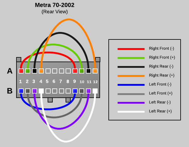
The next step is to reinstall the wiring between the Metra 70-2002 connector and the Metra 71-2002 connector. The wiring diagram below is what we will be building.
;)
Wiring Connection Legend
- Right Front (Negative) - [70] A1 to [70] A9 - RED
- Right Front (Positive) - [70] A2 to [70] A10 - GREEN
- Right Rear (Negative) - [70] A3 to [70] A11 to [71] A11 - BLACK
- Right Rear (Positive) - [70] A4 to [70] A12 to [71] A12 - ORANGE
- Power Antenna - [70] A5 to [71] A5 - YELLOW
- Left Front (Negative) - [70] B1 to [70] B9 - BLUE
- Left Front (Positive) - [70] B2 to [70] B10 - GRAY
- Left Rear (Negative) - [70] B3 to [70] B11 to [71] B11 - PURPLE
- Left Rear (Positive) - [70] B4 to [70] B12 to [71] B12 - WHITE
WIRE 1 - RIGHT FRONT SPEAKER - NEGATIVE (A1 to A9)
Note that the red wire removed from the Metra 70-2002 Connector includes three pins and two short and one long wire segments. Cut the second short wire segment as close as possible to the pin connector so that you have a single short segment with two pins attached. Next, insert the pins into the rear of the Metra 70-2002 Connector in positions A1 and A9. If the pin does not stay in place, you may need to take the screwdriver and bend the clasp on the pin back so that it can catch properly.
;) (click any image above to enlarge)
(click any image above to enlarge);)
;)
WIRE 2 - RIGHT FRONT SPEAKER - POSITIVE (A2 to A10)
Wire 1 was the easy one, the remaining wires will have to be soldered together (or connected using an alternate electrical connector). Basically we need to connect two of the wires with pins together to create a single wire with a pin on each end. Wire two is a simple straight connection using the green and green with black stripe wire leads from the Metra 70-2002 connector. I trimmed the lengths down to eliminate bulk, but that is optional. Cut, strip the insulation and solder the two ends of the green leads so that you end up with a single wire with a pins on each end. Insert a length of heat shrink tubing around the connection and heat to shrink. Finally insert the pins into position A2 and A10 of the Metra 70-2002 connector.
;) solder two leads
solder two leads
;) place heat shrink
place heat shrink
;) heat to shrink
heat to shrink
;) insert into connector
insert into connector
WIRE 3 - RIGHT REAR SPEAKER - NEGATIVE (A3 to A11 to A11)
Wire 1 and wire two were straight connections that bypass the factory amplifier completely. Wire three is slightly different because it also feeds the amplifier the rear audio signal so that the factory amplifier can drive the cargo area subwoofer and pillar tweeters. If you do not want to use the factory amplifier at all you can leave out the A11 connection to the Metra 71-2002. The next wire is a connection using the black and black with white stripe wire leads from the Metra 70-2002 connector and the black wire from the Metra 71-2002 connector. Cut, strip the insulation and solder the three ends of the black leads so that you end up with a wire with two Metra 70-2002 pins and one Metra 71-2002 pin. Before soldering make sure to stage a length of heat shrink tubing around the connection and after soldering slide the heat shrink tubing into place and heat to shrink. Finally insert the pins into position A3 and A11 of the Metra 70-2002 connector and also A11 of the Metra 71-2002 connector.
;) 70-2002 close up
70-2002 close up
;) both connectors
both connectors
;) 71-2002 close up
71-2002 close up
WIRE 4 - RIGHT REAR SPEAKER - POSITIVE (A4 to A12 to A12)
Repeat the same steps as wire three using the orange and orange with yellow stripe wire leads. Insert the pins into position A4 and A12 of the Metra 70-2002 connector and also A12 of the Metra 71-2002 connector.
;) 70-2002 close up
70-2002 close up
;) 71-2002 close up
71-2002 close up
WIRE 5 - POWER ANTENNA (A5 to A5)
Wire 5 is a simple straight through connection from A5 of the Metra 70-2002 connector to A5 of the Metra 71-2002 connector using the yellow wire leads
;) 70-2002 close up
70-2002 close up
;) 71-2002 close up
71-2002 close up
WIRE 6 - LEFT FRONT - NEGATIVE (B1 to B9)
WIRE 7 - LEFT FRONT - POSITIVE (B2 to B10)
Wire 6 and 7 are both simple straight bypass connection just like wire 1 and 2 except that they are installed on the "B" side of both connectors. Wire 6 uses the blue with yellow strip and the tip of the red wire from the Metra 70-2002 connector. There were not two blue leads and we need to reuse every pin, so I used just the tip of the remaining red wire lead and trimmed off the extra red wire. See the photo for details. Wire 6 should be inserted into positions B1 and B9 on the Metra 70-2002 connector. Wire 7 uses the gray and gray with black strip wire leads from the Metra 70-2002 connector and should be inserted into positions B2 and B10 on the Metra 70-2002 connector.
;) Wire 6 - Blue
Wire 6 - Blue
;) Wire 7 - Gray
Wire 7 - Gray
WIRE 8 - LEFT REAR - NEGATIVE (B3 to B11 to B11)
WIRE 9 - LEFT REAR - POSITIVE (B4 to B12 to B12)
Wire 8 and 9 are identical to wires 3 and 4 except that they are installed on the "B" side of both connectors. These wires provide the rear audio signal for the factory amplifier to deliver sound to the factory subwoofer and pillar tweeters in the cargo area. Wire 8 uses the purple and purple with black stripe wire leads from the Metra 70-2002 connector and the purple with black stripe wire from the Metra 71-2002 connector. Wire 8 should be inserted into positions B3 and B11 on the Metra 70-2002 connector and position B11 on the Metra 71-2002 connector. Wire 9 uses the white and white with black stripe wire leads from the Metra 70-2002 connector and the white wire from the Metra 71-2002 connector. Wire 9 should be inserted into positions B4 and B12 on the Metra 70-2002 connector and position B12 on the Metra 71-2002 connector.
;) Wire 8 (70-2002 close up)
Wire 8 (70-2002 close up)
;) Wire 8 (71-2002 close up)
Wire 8 (71-2002 close up)
;) Wire 9 (70-2002 close up)
Wire 9 (70-2002 close up);) Wire 9 (71-2002 close up)
Wire 9 (71-2002 close up)
WIRING COMPLETE
That all the wiring steps, next, we will test the connections and complete the assembly.;) Wiring Completed (click image to enlarge)
Wiring Completed (click image to enlarge)
<< STEP 4 >> - Testing
If you have a multi-meter or continuity tester, its a good idea to test all the pins to make sure that the connectors are wired correctly before installing into the Tahoe. Set the multi-meter to continuity testing mode and then test the following pins in the Metra 70-2002 connector and make sure there is a connection between them. Also touch the other pins to ensure that no other pins have a connection for each test.
- A1 to A9
- A2 to A10
- A3 to A11
- A4 to A12
- B1 to B9
- B2 to B10
- B3 to B11
- B4 to B12
Next let's test the Metra 71-2002 connector. To do this you can use the small paper clip to insert into each pin for testing. Ensure the following connection are valid:
- Metra 70-2002 A5 to Metra 71-2002 A5
- Metra 70-2002 A11 to Metra 71-2002 A11
- Metra 70-2002 A12 to Metra 71-2002 A12
- Metra 70-2002 B11 to Metra 71-2002 B11
- Metra 70-2002 B12 to Metra 71-2002 B12
;) Multi-meter / Continuity tester
Multi-meter / Continuity tester;) test Metra 70-2002
test Metra 70-2002;) test Metra 71-2002
test Metra 71-2002
<< STEP 4 >> - Tidy Up
All tests passed? Great! Let's finish by re-installing the retention clips in the Metra 71-2002 connector and and adding a few nylon wire ties to tidy up this bypass connector.
;) blue clip
blue clip;) gray clip
gray clip;) Metra 71-2002 - complete
Metra 71-2002 - complete
Install a few nylon tie straps and trim all the excess strapping.
;)
Installation
Now that your have constructed the bypass adapter, the installation inside the truck is very simple. Empty the glove box and then depress the right side towards the drivers side of the vehicle to allow the glove box door to open completely and drop open.
Next, locate the factory amplifier directly to the right of the cabin air filter on the right side of the glove box cavity.
;)
;)
Next, release the mounting retention clip located on top of the amplifier.
;)
;)
Tilt the amplifier up to gain easier access to the wiring connectors plugged into the amplifier. Unplug the lower wiring connector from the amplifier. There is a release on the back side of the connector, you must depress this release before the plug can be removed from the amplifier.
;)
;)
Insert the Metra 70-2002 connector on the bypass adapter into the vehicles wiring harness. Insert the other end of the bypass adapter (the Metra 71-2002 connector) into the factory amplifier. Don't worry, you can't screw this up, the plugs only fit in their correct locations.
;)
;)
Tuck the bypass adapter away above the amplifier so that does not interfere with the glove box. Put the amplifier back in place and re-attach the retention latch and then raise the glove box and fire up your stereo for a test. That's it -- we are all done!
;)
More Information / Source
More information about the wiring harness in the Tahoe and more specific details about this adapter can be found in this document:
Please note: the wiring coloring scheme used in this document is different than what is posted in this article. The article used the best mix of colored wires based on what came in the Metra connector packages and trying to remain as consistent as possible for all connection leads.
This document was originally posted on this forum posting:
 Robert Savage
If you are not interested in using the 2002 Tahoe's factory amplifier, rear pillar tweeters, and factory sub, then you only need the Metra 70-2002 connector and not the Metra 71-2002.
The wiring is bascially the same except that no wire leads extend to the second connector. This version of the adapter just bypasses the factory amplifier/crossover and sends the pure unfiltered audio signals to all the door speakers.
UPDATE 2019-07-02
A number of user comments suggest that you can simply purchased Metra #70-2021 if you wish to do a complete bypass of the factory amp. I have not personally verified or tested this, but it may be worth a try or further investigation for an easier off-the-shelf install.
Reader Comments (159)
So I adapted this to work with my 2004 Silverado and my friend did it on his 2003 with rear audio and Bose 7 speaker. Here are the main differences:
The amp is located in the center console not behind the glove box.
The 70-2002 leaves you a wire short so you should order two so you have enough pins.
The pin locations within the plug are in completely different locations than the Tahoe.
With a copy of the factory wiring diagram you can easily identify the correct pin locations. Other than the pin locations the connections themselves are identical. We also tied in from the 70- to the 71- the three wires to the rear audio system just in case since we had the extra wires due to ordering a second 70- plug.
My stereo has never sounded better and still has all the factory speakers, and the bass actually hits harder than you'd think.
Thanks for the starter on the jumper and with a little research we were able to adapt it for other vehicles.
I bought two 70-2002 and one 71-2002. From the quantity of wires from the two 70-2002 connectors I was able to use the correct color wires for the speakers to match the factory harness. Maybe I'm just picky. All I can say is 'Wow!!". This really increased the quality of the sound of the aftermarket Kicker dual speakers I put in the front and rear. Before the harness the sound was missing the bass from the four new door speakers. Now it just sounds much, much better. The old speakers were all torn including the subwoofer. I bought an MB Quart DS1-204 to replace the 8" subwoofer. It can only sound even better. I'm 64 so I don't need a lot from my sound system. Next is a double din to put in the 01 Suburban. Picked up the overpriced Metra kit but what the heck, I don't feel like hacking up the dash, maybe just the radio bracket. That should finish up the entertainment system. Sure I could have gone with components but I'm enjoying just the bypass improvement. I have some extra connector wires from both connectors but the 70-2002 wires are probably the ones someone would need. I'll keep an eye on this for awhile. I'll receive notifications via email. Thanks.
Hi M. Savage and all people,
I am french and my name is valerie. I recently bought a 2002 suburban because I love this car. unfortunatly several things didn't work, specially the radio. I knew that and this is the reason why the price was lower. I thought that I could repair this with a specialist but in my area No one wants to bother trying to repair. So I try to explain you my problem :
So the radio give no sound. It is the factory radio with cd player and above tape player. For peoples behind there are connections for headphones and sound control.
This is no bose system and I haven't Steering wheel controls.
We have another car a chevrolet venture who have the same radio. So we mounted the sub radio on the venture and there was a lot of sound.
We have check the fuse, there was ok.
So I have read forum in US and I have discovered that there was an amplifier in the sub behind the glovebox.
I wanted to change my amp because I think that it is the reason why I have no sound. I have find one (the same exactly) in ebay. I explain my problem with the seller and he tell me that if I change the amplifier I must have ODB tech II to program the amp with BCM.
So again I have read different discussion and I find two documents :
http://z71tahoe-suburban.com/iboard/index....=post&id=29
http://www.savagehomeautomation.com/projec...hevy-tahoe.html
You have the solution for bypass amp but I can't realise the harness because it's too difficult for me.
So my question is : Is there anyone who could make it for me. I have a paypal account and I can pay with it. please.
another question : what kind of harness is plug and play for a new radio (one din is good for me)
thanks a lot for your help and your answers
Valerie. The factory sound system has more than one fuse in order to function. One is the radio fuse on the side panel of the dash and the other is under the hood on the left hand side fuse box labelled RDO AMP 25, a 25 amp fuse. Make sure both fuses are good and working. A meter or test light would also verify power. Checking them both with the ignition key on and off. I'm basing my comments on my experience with my 2001 Suburban 2500 and am not certain it applies to your Suburban, hopefully it does. If not, then maybe someone else will chime in. If you have power but no sound you may have a bad amplifier in which case bypassing it may be the best way. Building a bypass harness like the one in this web page and installing it may end up a couple of ways. One, you may not get any sound because the cure for your problem could be in the factory wiring going to or leaving your radio or amp such as cut or modified wires. Two, the bypass will cause sound to come out of your front and rear speakers (if equipped) but not the sub-woofer or tweeters at the rear because the amplifier is bad or there is no power going to it. This is provided the factory radio is being used and the plugs and wiring that are plugged into the back of it are intact and all seated or plugged in. I can certainly make you a harness like the one in this web page. I would make sure your are good and you have power to the radio and amp. You know your radio is good so it has to be wiring, fuses or a bad amp. The bypass may solve your problem but you may not get any sub-woofer and rear pillar tweeters if you Suburban has them. But maybe all you want is some sound to come out of the speakers to start. Let me know how to contact you. Art
Just an afterthought. I'm running an aftermarket head-unit but still using the factory sub woofer/tweeter amp for the rear speakers in the sub-woofer box and rear tweeters in the rear pillars. The factory amp needs to be powered from the blue/white HU wire, typically for switched DC power for amps etc. The other connector that was removed from the factory radio has a pink wire that needs to be powered when the radio is turned on. Connect the blue/white wire to the pink wire and the factory amp will work. If you're eliminating the factory amp completely it won't matter. I know this is an old thread but I thought I add my .02 cents.
Hi Art and First many thanks for your answers.
I have check fuses with a multimeter and they are Ok. But I don't know how I can do for check the power at the level of the amp. it difficult to explain in english but I would like to know if the power arrive in the amp. there is a amp in ebay about 100 dollar but I must be sure that it's really the amp who is wrong. arggggg......
I have found the wires pink and blue white but I don't dare cuting the wires.
What kind of aftermarket radio have you got in your sub?
All I want is sound for music (perhaps usb and audio jack for playlist) but I like when there is good sound. In my very old venture there is a good sound with good bass (factory radio) and I'm not sure there is an amp in this car.
you can contact me in my email valerie.wozny@free.fr
have a good day
Hi it's me again. So I have connected blue/white wire with pink wire. When I connect I hear a "boum" in the subwofer but no sound with the radio. but now we know that the power arrives up the ampli. I don't know what I have to do for the next step :(
Hey guys can anyone provide me with a clear photo of a wiring diagram of which colors go into which connectors on the oem pigtail? I basically need a clear photo of the oem connected that goes into the amp so that I can figure out which position each color goes into. I really need to see the 8 speaker color wires. Will send $5 via PayPal for the correct photo.
You can reach me at abe@5r4.com
Followup: I was able to provide Valerie from France a bypass harness that worked enabling the OEM headunit to deliver sound to the factory door speakers which weren't working prior to the harness. I don't think the subwoofer and tweeters are working still. Prior to the new harness install; no sound was being delivered to any speakers. It may be the amplifier itself, power to the amp, the rear wiring or speakers that are bad. At least there is now sound to the door speakers even if they do require an upgrade due to torn paper cones which do occur over time in these vehicles.
Hello,
I was able to use this post to upgrade/update the sound in my 2002 Suburban LT. I replaced all four door speakers with inexpensive 6.5" ones. I used 3 way Rockford Fosgates up front.
https://www.amazon.com/gp/product/B00BF6HWCM/ref=oh_aui_search_detailpage?ie=UTF8&psc=1
and Kenwood Road Series in the back.
http://www.bestbuy.com/site/kenwood-road-series-6-1-2-2-way-car-speakers-with-paper-woofer-cones-pair-black/3190025.p?skuId=3190025
I also bought a BOSS Audio CX8 400 Watt, 8 Inch, Single 4 Ohm Voice Coil Car Subwoofer and a BOSS Audio R1002 Riot 200 Watt, 2 Channel, 2/4 Ohm Stable Class A/B, Full Range, Car Amplifier for the back.
The Boss CX8 works great as a replacement speaker. I had to drill new mounting holes but it was no problem as the sub box is made of hard plastic. For anyone having trouble finding a compact speaker to fit this enclosure, get this one. There is a soft rubber trim/bumper piece that goes all the way around the speaker. Remove this and replace it backwards. It's really easy. Better yet remove it completely and mount the speaker in front of it so that the trim piece fits between the speaker and the sub box. This will give you that extra 1/4" so that the coil doesn't rest on the back of the sub box.
So far I have not installed the amp and I'm using the factory amp to power the new sub and the factory rear pillar speakers. It seems to be working great so far. I'm even considering using the bypass harness to bypass the sub wiring and let the new Kenwood head unit do the sub work. Can anyone tell me what additional wires or changes will need to be made so that the Subwoofer bypasses the amplifier in the same way the door speakers do? So that the only speakers powered by the factory amp would be the rear pillars.
Also, here's a link to the factory wiring including the amp for the non-Bose Suburban.
<https://static.cargurus.com/images/site/2015/04/10/18/25/pic-7513991301466613218-1600x1200.jpeg>
Thanks again for the write up. It saved me a ton of $$$
Thanks very much for taking the time to create such a great "tutorial" on how to do this hack. I've read the whole thing and looked at a lot of the posts, but haven't yet stumbled across any answer to a couple questions.
I already replaced all four OE door speakers on my 2001 Suburban about 10 years ago, without messing with the factory (Delco) head unit, rear pillar speakers or the cargo area sub (On-Star, non-Bose system) ... Infinity components in front doors, Infinity "shallow mount" coaxials in the rear doors. They've worked great all this time, but I finally blew the driver side front woofer, I think, due to years of underpowering from the factory amp. I've already ordered a pair of replacements for both front doors.
My question (and it may be a dumb one, so bear with me) is this: It's my understanding that what you're doing with this hack is sending the output for the front and rear doors directly from the head unit to the speakers, right? Is there an amp in the OE Delco head unit with sufficient power to drive all four door speakers, e.g., without any help from the separate factory amp you're bypassing? Assuming there is, does anyone know how much power the 2000-2001 OE Delco head unit would send to the doors via this bypass/connection?
The reason I ask is that if it turns out that power level is insufficient, I'm thinking about placing a 4-channel amp (Clarion XC1410) between this bypass and the door speakers, just to boost the power to around 50W RMS per speaker, but I probably wouldn't bother with that if the native power from the head unit is sufficient ...
Mark, I'm doing exactly what you're asking about. Powering the aftermarket front and rear door speakers with the factory head unit. I like the sound and it does get loud enough. Plus the rear subwoofer and rear pillar speakers are still working as originally designed and are not bypassed. I guess you could add a high level input amplifier to drive the speakers. I believe the next upgrade would be a new head unit, amplifier, and subwoofer. From what I've read the original purpose of the bypass was to drive aftermarket speakers with the factory head unit and bypass the function of the amplifier and what impact it has on the aftermarket speakers which, in my case, was a filtering out of the bass. Bypassing the amp increased the bass response going to the aftermarket to a very acceptable and pleasant level without having to add a bunch of components. You can't go wrong with the bypass. Try it first, I liked it. Hope this helps.
Thanks, Renoman ... when I originally replaced the OE door speakers I didn't mess with the rear pillar speakers and sub, but I AM changing those out this time ... the cone on the OE sub is totally gone after 16 years ... can you imagine? Yeesh.), and I want to hear what the OE system sounds like with these improvements. I'll do that first, then decide on the bypass, then decide on the amp. In the meantime, I'd still like to know what the OE head unit is sending to the doors ...
I think you should do the bypass. It's really inexpensive to do. You'll be amazed at the improvement. I changed out my subwoofer speaker I bought either at Walmart online or Amazon online. The tweeters were still good. It made a huge difference with new speakers, the bypass, all working from the factory head unit. I think the replacement subwoofer was about $50. I did notice there are at least two types of subwoofer speaker enclosures. One is mounted low and in the other the speaker is mounted high. Mine is low and is almost as low as the floor. Anyway, make sure you buy the correct size, it's easy to get the wrong one. Mine is a 2001 Suburban 2500 4WD LT. I can help with finding what I ordered and with a bypass.
Hi. I am trying to do this bypass on my 2003 Yukon Denali and i am having trouble with figuring out where the pins go from the 70 series harness to the 71 series harness in relation to those locations denoted with a letter. I was able to match up most pins with corresponding locations, for instance pins A1 and A9 fare A10 and B3 for my truck. But when it comes to pins B3 and B11, for my truck it is A4 and D if I am not mistaken. I have no clue as to what location the D pin is supposed to go on the 71 harness. Has anyone done this harness on a Bose Lux amp in the center console? Any help would be greatly appreciated.
Carlos
@ Renoman (and anyone else thinking about adding this bypass harness for a 2001 Suburban, non-BOSE, OnStar, no steering wheel controls, center console controls for rear seat passengers), the procedure/harness described simply doesn't work right in this particular vehicle/accessory configuration. It's close, but something's missing/incorrectly wired. With the harness in place, the right front door speaker is dead, along with the rear pillars and subwoofer. When I take the bypass out, everything works normally, and with the addition of a Rockford Fosgate shallow-mount sub to replace the totally blown/disintegrated paper cone OE sub, I'm not missing any bass now anyway, that's for sure.
Another problem is the current Metra 70 harness doesn't include the number of wires described in the procedure, so you're always going to be short a couple of wires with pins on them. I had to go and pay retail (13.99) for a generic harness just to get the extra wires with pins that I needed to complete the assembly, so my total outlay was about $35 (excluding all the time spent screwing around with it), all for a harness/hack that doesn't work.
On the positive side, now I've got all the freaking wires I need to reconfigure the harness ... if anyone out there has figured out how to make it work correctly with the 2001 Suburban I've described ...
Mark, I have helped Valerie in France who has the same setup as yours. Same as mine but I have no rear controls. I made hers and mine identical and it works. I would ensure the wiring of the pins are identical to the sketch or pics. It might be you're not getting power to the subwoofer on the pins the 71-2002 connector. If you'd like to send me a pic; you can to renoman@prodigy.net. I'll look at it. This is if you're using the stock head unit.
My 2002 burban with bose, had a separate harness for the tape deck (which is where that pink AMP power wire is found) on the HU , As I followed instructions for the bypass and worked perfectly with an Absolute dvd bt HU , I Spliced into that pink wire with my Blue power antenna wire also referred to as remote power for amps and such. Also 2002 calls for a special HU kit for double din which is about $150 my HU is not double din but the screen is so installed kit part # scosche GM1484B 1995-98 full size truck eq kit ,Also had to modify it so it would work upside down, as this also allowed me to "cheat" the left side of my digital display to suit passengers better. A+++ better then the kit it calls for.
Dan, I had to do the same thing with my double-din, splice into the pink wire of the harness that went to the cassette player. Splicing into the pink wire with the antenna or amp wire isn't required if the original head unit is being used and the bypass installed.
Yes,I deleted my console a few months ago and replaced with a jump seat as I had my rear stereo controls sandwiched between the floor and jump seat in the rear as for the tape deck it did not make a come back but I noticed that it had the same pig tail as the secondary harness on the radio I believe this also where OnStar feeds into but not entirely sure. As for my OnStar does make a peep anymore. As far as permenently modifying wires on the burb' it was only a scab to pink power to remote on stereo harness side and nice grounding wire that was also scabbed to the ground in that "tape deck harness" and others, I wasn't even going to attempt an upgrade until I came across this well thought out and wonderful right up ,I also got the HU as a gift and it sat in a file cabinet for about a year. I am so happy with all this that I have ordered a backup camera and a 21 inch tft flip down monitor. I am also digging up info on another car with Audi Delta with Bose and cd changer, Also thought to unupgradeable. I WILL part with 2002 oem suburban CD player and complete console with keys.