


Bypass Factory Amp/Crossover in 2002 Chevy Tahoe

This article strays a bit from home automation, but it was a small project that I completed recently and felt that others could benefit from a detailed write up with step-by-step instructions and pictures.
I recently found myself needing to replace almost every speaker in my 2002 Chevy Tahoe (non-Bose sound system). The factory speakers were all blown and sounding pretty pitiful. In fact I did not realize how bad it was until I removed the old factory speakers and noticed cone separation on every door speaker and the factory subwoofer.
In addition to replacing the speakers, I came across a forum post on z71tahoe-suburban.com that discussed bypassing the factory amplifier for each of the door speakers. It turns out that all the door speakers are routed thru the factory amplifier. I am not sure that it provides amplification to the door speakers, but it does have an internal crossover that removes much of the bass from the audio signal. Since I replaced all the door speakers with a better set of component speakers capable of handing more of the full audio range, I did not want the factory amp/crossover restricting the audio signal from the head unit (receiver) to the door speakers.
The forum post included a detailed set of instructions on how to build an adapter cable that will plug directly into the factory wiring harness and the factory amplifier and bypass the factory crossover for the four door speakers. This bypass cable does still send audio and power to the factory amplifier for the rear cargo area subwoofer and pillar tweeters. (If you don't need the factory amp because you are using an after-market amplifier, then you may choose not to include that portion of the cable or just not plug the adapter back into the factory amplifier.) This is a 100% non destructive modification to the Tahoe. This bypass adapter can be removed at any time.
Parts List
;) (click image to enlarge)
(click image to enlarge)
The following parts are required.
Approximate Cost: $20-25 USD
Total Time: 1-2 hours
NOTE: You may notice that these wiring adapters describe that they are for a Saturn vehicle. Just ignore that, we are not going to use them as they are wired, we are going to reconfigure the wiring. We just need these as they are the correct connectors that will work with the Tahoe's factory wiring harness and factory amplifier.
Tools & Supplies
I used the following tools and supplies to complete this project:
;) (click image to enlarge)
(click image to enlarge)
- Wire Cutters
- Wire Strippers
- Small Flat Screwdriver
- Small Paperclip
- Large Paperclip
- CD/DVD Drive Eject/Release Tool (optional)
- Solder Iron
- Solder
- Solder Paste (optional)
- Small Nylon Wire Ties (optional)
- Assorted sized and color heat shrink tubing
- Heat Gun (or hair dryer, or cigarette lighter)
- Digital Multi-meter for continuity testing (optional)
- Table/Bench Vise (optional)
- Helping Hands with Alligator Clips (optional)
NOTE: If you are not comfortable with soldering, you could use wire nuts (twist on wire connectors, b-caps) instead to make each wiring connection. This take up more room, but is perfectly viable. Just make sure to use electrical tape or some means to ensure that the wire connectors don't vibrate loose and fall off over time.
Assembly
We are basically going to use the two Metra GM connectors to create a bypass cable that will be installed in between the Tahoe's factory wiring harness and the factory amplifier/crossover.
<< STEP 1 >> - Disassemble the Metra 70-2002 Connector
The first step is to remove all the existing pins and wires from the Metra 70-2002 connector. The pins are released by inserting a small paperclip below each pin and using a push and pull technique on the wire until the pin is released. Don't use force to remove these pins, we will need to reuse each pin and wire.
;) (click any image above to enlarge)
(click any image above to enlarge);)
;)
<< STEP 2 >> - Disassemble the Metra 71-2002 Connector
The next step is to disassemble the Metra 71-2002 connector. Before removing the pins and wires, we must first remove the two retaining clips (gray and blue). Lets start with the gray clip. Gently insert the end of a small flat screwdriver between the connector and the clip's retention clasp. Repeat this for each side of the clip. Once released, pull the clip towards the rear of the connector to remove it. Next we need to remove the blue clip. For the blue clip we must insert the end of the screwdriver to release the retention clasp from the front side of the connector. Repeat this on both sides and then gently pull back the clip towards the rear of the connector to remove it.
;)
;)
;)
;)
(click any image above to enlarge)
With the two clips removed, we can now remove each pin and wire. To remove the pins in this connector, insert either the end of the large paper clip or the end of a CD/DVD disc removal tool into the face of the connector as show below to release the pin. (I found that the diameter of the CD/DVD disc removal tool was slight larger than the paperclip and was a little easier to use.) Use the push and pull technique on the wire to remove it from the connector. Again, don't use force to remove these pins, we will need to reuse a few of the pins and wires. The pins will easily slide out towards the rear of the connector once properly released.
;)
;)
;)
;)
(click any image above to enlarge)
<< STEP 3 >> - Rewire the Connectors
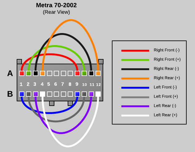
The next step is to reinstall the wiring between the Metra 70-2002 connector and the Metra 71-2002 connector. The wiring diagram below is what we will be building.
;)
Wiring Connection Legend
- Right Front (Negative) - [70] A1 to [70] A9 - RED
- Right Front (Positive) - [70] A2 to [70] A10 - GREEN
- Right Rear (Negative) - [70] A3 to [70] A11 to [71] A11 - BLACK
- Right Rear (Positive) - [70] A4 to [70] A12 to [71] A12 - ORANGE
- Power Antenna - [70] A5 to [71] A5 - YELLOW
- Left Front (Negative) - [70] B1 to [70] B9 - BLUE
- Left Front (Positive) - [70] B2 to [70] B10 - GRAY
- Left Rear (Negative) - [70] B3 to [70] B11 to [71] B11 - PURPLE
- Left Rear (Positive) - [70] B4 to [70] B12 to [71] B12 - WHITE
WIRE 1 - RIGHT FRONT SPEAKER - NEGATIVE (A1 to A9)
Note that the red wire removed from the Metra 70-2002 Connector includes three pins and two short and one long wire segments. Cut the second short wire segment as close as possible to the pin connector so that you have a single short segment with two pins attached. Next, insert the pins into the rear of the Metra 70-2002 Connector in positions A1 and A9. If the pin does not stay in place, you may need to take the screwdriver and bend the clasp on the pin back so that it can catch properly.
;) (click any image above to enlarge)
(click any image above to enlarge);)
;)
WIRE 2 - RIGHT FRONT SPEAKER - POSITIVE (A2 to A10)
Wire 1 was the easy one, the remaining wires will have to be soldered together (or connected using an alternate electrical connector). Basically we need to connect two of the wires with pins together to create a single wire with a pin on each end. Wire two is a simple straight connection using the green and green with black stripe wire leads from the Metra 70-2002 connector. I trimmed the lengths down to eliminate bulk, but that is optional. Cut, strip the insulation and solder the two ends of the green leads so that you end up with a single wire with a pins on each end. Insert a length of heat shrink tubing around the connection and heat to shrink. Finally insert the pins into position A2 and A10 of the Metra 70-2002 connector.
;) solder two leads
solder two leads
;) place heat shrink
place heat shrink
;) heat to shrink
heat to shrink
;) insert into connector
insert into connector
WIRE 3 - RIGHT REAR SPEAKER - NEGATIVE (A3 to A11 to A11)
Wire 1 and wire two were straight connections that bypass the factory amplifier completely. Wire three is slightly different because it also feeds the amplifier the rear audio signal so that the factory amplifier can drive the cargo area subwoofer and pillar tweeters. If you do not want to use the factory amplifier at all you can leave out the A11 connection to the Metra 71-2002. The next wire is a connection using the black and black with white stripe wire leads from the Metra 70-2002 connector and the black wire from the Metra 71-2002 connector. Cut, strip the insulation and solder the three ends of the black leads so that you end up with a wire with two Metra 70-2002 pins and one Metra 71-2002 pin. Before soldering make sure to stage a length of heat shrink tubing around the connection and after soldering slide the heat shrink tubing into place and heat to shrink. Finally insert the pins into position A3 and A11 of the Metra 70-2002 connector and also A11 of the Metra 71-2002 connector.
;) 70-2002 close up
70-2002 close up
;) both connectors
both connectors
;) 71-2002 close up
71-2002 close up
WIRE 4 - RIGHT REAR SPEAKER - POSITIVE (A4 to A12 to A12)
Repeat the same steps as wire three using the orange and orange with yellow stripe wire leads. Insert the pins into position A4 and A12 of the Metra 70-2002 connector and also A12 of the Metra 71-2002 connector.
;) 70-2002 close up
70-2002 close up
;) 71-2002 close up
71-2002 close up
WIRE 5 - POWER ANTENNA (A5 to A5)
Wire 5 is a simple straight through connection from A5 of the Metra 70-2002 connector to A5 of the Metra 71-2002 connector using the yellow wire leads
;) 70-2002 close up
70-2002 close up
;) 71-2002 close up
71-2002 close up
WIRE 6 - LEFT FRONT - NEGATIVE (B1 to B9)
WIRE 7 - LEFT FRONT - POSITIVE (B2 to B10)
Wire 6 and 7 are both simple straight bypass connection just like wire 1 and 2 except that they are installed on the "B" side of both connectors. Wire 6 uses the blue with yellow strip and the tip of the red wire from the Metra 70-2002 connector. There were not two blue leads and we need to reuse every pin, so I used just the tip of the remaining red wire lead and trimmed off the extra red wire. See the photo for details. Wire 6 should be inserted into positions B1 and B9 on the Metra 70-2002 connector. Wire 7 uses the gray and gray with black strip wire leads from the Metra 70-2002 connector and should be inserted into positions B2 and B10 on the Metra 70-2002 connector.
;) Wire 6 - Blue
Wire 6 - Blue
;) Wire 7 - Gray
Wire 7 - Gray
WIRE 8 - LEFT REAR - NEGATIVE (B3 to B11 to B11)
WIRE 9 - LEFT REAR - POSITIVE (B4 to B12 to B12)
Wire 8 and 9 are identical to wires 3 and 4 except that they are installed on the "B" side of both connectors. These wires provide the rear audio signal for the factory amplifier to deliver sound to the factory subwoofer and pillar tweeters in the cargo area. Wire 8 uses the purple and purple with black stripe wire leads from the Metra 70-2002 connector and the purple with black stripe wire from the Metra 71-2002 connector. Wire 8 should be inserted into positions B3 and B11 on the Metra 70-2002 connector and position B11 on the Metra 71-2002 connector. Wire 9 uses the white and white with black stripe wire leads from the Metra 70-2002 connector and the white wire from the Metra 71-2002 connector. Wire 9 should be inserted into positions B4 and B12 on the Metra 70-2002 connector and position B12 on the Metra 71-2002 connector.
;) Wire 8 (70-2002 close up)
Wire 8 (70-2002 close up)
;) Wire 8 (71-2002 close up)
Wire 8 (71-2002 close up)
;) Wire 9 (70-2002 close up)
Wire 9 (70-2002 close up);) Wire 9 (71-2002 close up)
Wire 9 (71-2002 close up)
WIRING COMPLETE
That all the wiring steps, next, we will test the connections and complete the assembly.;) Wiring Completed (click image to enlarge)
Wiring Completed (click image to enlarge)
<< STEP 4 >> - Testing
If you have a multi-meter or continuity tester, its a good idea to test all the pins to make sure that the connectors are wired correctly before installing into the Tahoe. Set the multi-meter to continuity testing mode and then test the following pins in the Metra 70-2002 connector and make sure there is a connection between them. Also touch the other pins to ensure that no other pins have a connection for each test.
- A1 to A9
- A2 to A10
- A3 to A11
- A4 to A12
- B1 to B9
- B2 to B10
- B3 to B11
- B4 to B12
Next let's test the Metra 71-2002 connector. To do this you can use the small paper clip to insert into each pin for testing. Ensure the following connection are valid:
- Metra 70-2002 A5 to Metra 71-2002 A5
- Metra 70-2002 A11 to Metra 71-2002 A11
- Metra 70-2002 A12 to Metra 71-2002 A12
- Metra 70-2002 B11 to Metra 71-2002 B11
- Metra 70-2002 B12 to Metra 71-2002 B12
;) Multi-meter / Continuity tester
Multi-meter / Continuity tester;) test Metra 70-2002
test Metra 70-2002;) test Metra 71-2002
test Metra 71-2002
<< STEP 4 >> - Tidy Up
All tests passed? Great! Let's finish by re-installing the retention clips in the Metra 71-2002 connector and and adding a few nylon wire ties to tidy up this bypass connector.
;) blue clip
blue clip;) gray clip
gray clip;) Metra 71-2002 - complete
Metra 71-2002 - complete
Install a few nylon tie straps and trim all the excess strapping.
;)
Installation
Now that your have constructed the bypass adapter, the installation inside the truck is very simple. Empty the glove box and then depress the right side towards the drivers side of the vehicle to allow the glove box door to open completely and drop open.
Next, locate the factory amplifier directly to the right of the cabin air filter on the right side of the glove box cavity.
;)
;)
Next, release the mounting retention clip located on top of the amplifier.
;)
;)
Tilt the amplifier up to gain easier access to the wiring connectors plugged into the amplifier. Unplug the lower wiring connector from the amplifier. There is a release on the back side of the connector, you must depress this release before the plug can be removed from the amplifier.
;)
;)
Insert the Metra 70-2002 connector on the bypass adapter into the vehicles wiring harness. Insert the other end of the bypass adapter (the Metra 71-2002 connector) into the factory amplifier. Don't worry, you can't screw this up, the plugs only fit in their correct locations.
;)
;)
Tuck the bypass adapter away above the amplifier so that does not interfere with the glove box. Put the amplifier back in place and re-attach the retention latch and then raise the glove box and fire up your stereo for a test. That's it -- we are all done!
;)
More Information / Source
More information about the wiring harness in the Tahoe and more specific details about this adapter can be found in this document:
Please note: the wiring coloring scheme used in this document is different than what is posted in this article. The article used the best mix of colored wires based on what came in the Metra connector packages and trying to remain as consistent as possible for all connection leads.
This document was originally posted on this forum posting:
 Robert Savage
If you are not interested in using the 2002 Tahoe's factory amplifier, rear pillar tweeters, and factory sub, then you only need the Metra 70-2002 connector and not the Metra 71-2002.
The wiring is bascially the same except that no wire leads extend to the second connector. This version of the adapter just bypasses the factory amplifier/crossover and sends the pure unfiltered audio signals to all the door speakers.
UPDATE 2019-07-02
A number of user comments suggest that you can simply purchased Metra #70-2021 if you wish to do a complete bypass of the factory amp. I have not personally verified or tested this, but it may be worth a try or further investigation for an easier off-the-shelf install.
Reader Comments (159)
@ Renoman: I've checked all the connections multiple times against the Savage schematic and text descriptions, and they all match up ...
OK, Renoman ... I got the rear pillar speakers and sub to work with the bypass in place by reversing the polarities of their respective leads on the Metra 71-2002 connector, as follows (a deviation from the Savage schematic for the 2002 Tahoe):
A-3 to A-11 (on Metra 70) to A-12 on Metro 71
A-4 to A-12 (on Metra 70) to A-11 on Metro 71
B-3 to B-11 (on Metra 70) to B-12 on Metro 71
B-4 to B-12 (on Metra 70) to B-11 on Metro 71
I tried the same trick on the right front speaker (A-1, A-2 to A-9, A-10 on Metra 70) ... no luck. It still doesn't work with the bypass in place ... works fine without the bypass ...
@ Renoman (and all others trying this hack in a 2001 Suburban, On-Star, non-Bose). If you're losing the D-pillar speakers and sub, try reversing the polarities on their feed wires in the Metra 71 connector, as indicated in my immediately preceding post. I also figured out why I couldn't get the right front door speaker to work. The very first connection from the Savage schematic/plan is a red wire that already has three connection points/pins, and Robert instructs to snip off the extraneous lead, and use the remaining two pins. This wire is one of the two feeds for your right front door speaker. Unfortunately, in the wire I had, the makers apparently over-crimped the two point connection, partially severing the copper wire inside. When I tried removing it from the harness to check it, it actually broke off at the point where it meets the pin. I replaced this entire wire with a new, two-pin connector using some wires from the extra harness I bought, and PROBLEM SOLVED. The right front speaker came to life, and the whole thing's working great now. I'm now going to leave it in place for a week or two and see how I like the bypass sound in comparison to the OE ... so far, it's pretty spectacular ...
Mark, Great to hear. I really noticed the difference when I put in new door speakers and a new sub-woofer speaker. All of them were blown and after I put the new speakers in and before I put in the bypass I noticed there wasn't much bass in the door speakers. That's how I found this bypass thread. The bypass made a huge difference. I later put in a double din and had to use the antenna/amp power wire to tap into the pink wire from the cassette connector that was removed from the original radio. The pink wire is the power wire for the amp. I'm sure you'll enjoy the bypass.
So far, I've noted that Robert Savage's initial characterization of what the bypass does is accurate. The OE filter transfers most of the bottom end to the sub in the rear cargo area. The bypass returns a lot of low frequency to the door speakers (direct feed from the head unit), but leaves the sub intact, so, with broader range replacement speakers in the doors (I used Infinity components in the front, and Infinity coaxials in the rear), you get a fuller dynamic range spread more evenly through the whole system. It's pretty remarkable.
So I did this today - Thank ou for the article - this was awesome.
Quick question--- I never put the purple and the white and the 71-2002 - and I still have sound in my rear pillars and sub... I did do the black, orange and yellow though... Just wondering if these are 100% needed or not??
Thanks!
Interesting. I believe the feeds that run to the 71-2002 (with the exception of the yellow, "power antenna" lead) are a "bypass of the bypass," preserving the original wiring path to the rear pillars/sub. The real effect of the bypass is felt/heard in the door speakers only. I also believe that the signal going to the rear pillars AND sub in the original configuration is mono, not stereo. Therefore, it may be that the rear pillar speakers and sub will *work* with only two of the four diagrammed leads, BUT you may be losing half the signal strength that would otherwise be going to those speakers. No way to know that for sure without, e.g., measuring the current arriving at the pillars/sub under both configurations, to see if there's any difference. However, for anyone who doesn't want to bother with all that, I would err on the side of sending everything to the pillars/sub that the original configuration does, and the patch diagrammed by Savage does that. I had to buy an extra harness from Auto Zone to get all the patch wires needed to correctly complete this project ...
Thanks a million for this write up! I'm a DIY guy and your diagrams were perfect. Not to hijack but I wasn't able to find the 70-2002 harness locally but I instead used the Raptor brand PN # AT - WHGM3 which had the same connector shape from my local O'Reilly's. I only needed to get three extra wires / pins out off of a old donor harness I had laying around. Again thanks a million!
Just wanted to say thanks. Worked like a charm, the difference in sound quality was impressive. I have new head unit and now this bypass. Amp coming soon. You time doing this in such details was INVALUABLE. Thank you
Since this is the most active discussion on this topic, I wanted to chime in with a couple notes. First, thanks for the detailed write-up on this; just did the bypass on my '02 Yukon XL (along with new speakers in all four doors) and it works great.
The other thing I wanted to note is that I don't think the original PDF document is quite right in its description of how the D-pillar tweeters and sub are wired. It says that the tweeters and subwoofer share a single amp channel, the tweeters are wired in parallel with each other, and the subwoofer is wired in series with the tweeter pair. However, I don't believe this is correct for a couple of reasons. First, I cut one of the wires going to the subwoofer and the tweeters continued to work; if the sub and tweeters were wired in series, the tweeters should have stopped working along with the sub. Second, the electrical schematic of the system from Alldatadiy.com (see here: https://goo.gl/h36LnM - agrees with the Mitchell diagram posted above by Dokumentary) shows the tweeters wired in series with each other, not parallel, with the subwoofer signal on a separate set of pins/wires out of the amp. The schematic doesn't really provide any information about the inner workings of the amp, so the subwoofer and the tweeters could still be parallel internally and sharing a single amp channel (I'm sure there's a way to figure that out, just not sure what it is).
I was trying to track down exactly how these speakers are wired to determine what the long-term consequences might be of leaving the sub disconnected. My factory sub is shot and sounded terrible; I could live without a sub after doing the crossover bypass, but I'd really like to keep the D-pillar tweeters for the benefit of third row passengers - so I don't want to kill the amp by running without a sub. Failing to find any information about the inner workings of the amp/crossover unit (other than the seemingly incorrect info in the PDF), I decided the cheapest/easiest solution to give me peace of mind was to replace the factory sub with a Pyle PLPW8D. This sub sells for about $25, and is said to be a good replacement for the factory sub (using the factory spacer/trim ring between the speaker and the sub box to avoid bottoming out in the box); it has dual 4-ohm coils which can be wired in parallel to mimic the factory sub's 2-ohm impedance. This option gets me a working sub now and it's cheaper than replacing the amp later because I killed it by running with no sub.
I hope this information is helpful to somebody - just wanted to share a little more detail in case someone else has the same questions I did.
I'm trying to install a 5 channel amp and head unit into my 2004 Silverado with Bose system ran rca to amp the the four pair of speaker wires up to dash to tap into the factory speaker wire amp and radio come on sub comes on cannot get door speakers to come on but if I use a test speaker it works. So do I need to bypass factory amp not wanting to run all new wire
Will this work for an 03 Tahoe as well?
@ Thomas ... there are lots of '02 references in the preceding thread, the most recent being Isaac on Nov. 28, 2017, re his use of the bypass on a '02 GMC Yukon. Just try it ... the harnesses don't cost much, it's a fun little DIY project, and you won't be doing anything you can't easily undo if it doesn't work, or you decide you don't like the result.
@ Thomas: sorry for reference to Isaac's post ... I meant to refer you to an '03 post. Scroll through some of the earlier comments for '03 references. It really just depends on what your OE is. This hack is designed to bypass a factory amp that GM added to its OE head unit so that it would work better with a seven-speaker system ... two front doors (L/R), two rear doors (L/R), two rear pillars (mono) and one subwoofer (mono). The hack bypasses this amp to re-connect the door speakers directly to the head unit, and leaves the original connection in place for the rear pillars and subwoofer ... puts more of the bass from the head unit back into the door speakers.
Will I need the Metra 71-2002 for my 20002 Silverado 1500, since it doesn't have a factory rear sub or rear pillar tweeters?
Thank you so much for this article. I have a 2001 Chevy Tahoe with factory amp, pillar speakers,and sub woofer. When I installed a aftermarket stereo head and none of the speakers or the sub worked I thought I was going to have to spend a ton of money on new equipment and wiring. With this tutorial and the comment thread. I was able to work it out. A couple of points that have already been answered in the comments but were very helpful to me are as follows; 1. The Metra 70-2002 was lacking 3 wires and the corresponding pins. Order a cheap GM adapter and you will have plenty. 2. The original schematic did not work for my Tahoe. I did have to reverse the polarity of the 71-2002 by swapping the position of A11 and A12 Also B11 and B12 on the Metra 71-2002. 3. I also had to connect 12V accessory (blue wire white stripe from the head unit to the pink (power to amp) in order to make it all work. I learned a lot on this install and appreciate all the great information.
I have read through a ton of post and Im still not clear on what pins works for 03 yukon xl bypass. I have wired the harnesses to the original setup, can some let me know what needs to change.
Chris, the electronics changed significantly along with the interior refresh in 2003; the radio on 2003+ trucks is part of a "data bus" system and I believe it is integral to the function of the retained accessory power, warning chimes, and turn signal clicker. In the little bit of research I've done, I don't believe there is any easy way to bypass the factory amp while keeping the factory head unit. If you are swapping to an aftermarket head unit, you will likely need an interface adapter to retain the functions mentioned above and get the signal to the speakers. Which adapter you need will depend on what audio system (Bose vs not) is installed in your truck. I would start at Crutchfield.com; if you input your year/make/model and audio options into their compatibility tool, it will tell you which harness you need.
I have a aftermarket radio installed with aftermarket speakers. And yes it is using the amp integrated harness. I want to bypass the amp and sub because I only wanted to add a sub and gain full sound out of speakers without adding a four channel amp as well. I was hoping this would work. I also wanted to know if Im abke to use this bypass woukd i have to remove the integrated harness?
Chris, it has been a while since I have worked on a truck with a data bus system; I don't own one so it was just helping a friend with his. I believe that if you want to bypass the factory amp, you may have to run new wires from your head unit to the speakers. If I remember right, the adapters usually have their own little speaker built in for the chimes, etc., so I think you could disconnect the head unit's speaker outputs from the interface adapter and connect them to new wiring that you would run directly to the speakers. If you leave everything else (power, etc.) connected to the interface, I think your chimes, RAP, etc. would continue to work but your speakers would be getting the full range signal from your head unit. Don't quote me on this - but hopefully it's both correct and helpful!